Hello,
I have been working on creating an accurate Flow Simulation model of a real Garrett Compressor, specifically the GTX 5533R with a 85mm inducer. Here is a link to the compressor map https://www.garrettmotion.com/wp-content/uploads/2018/05/Comp-Map-GTX5533-85mm-1.jpg I am targeting 3PR, 14.7psi inlet, 44.1psi outlet, 110lb/min at 65000 RPM.
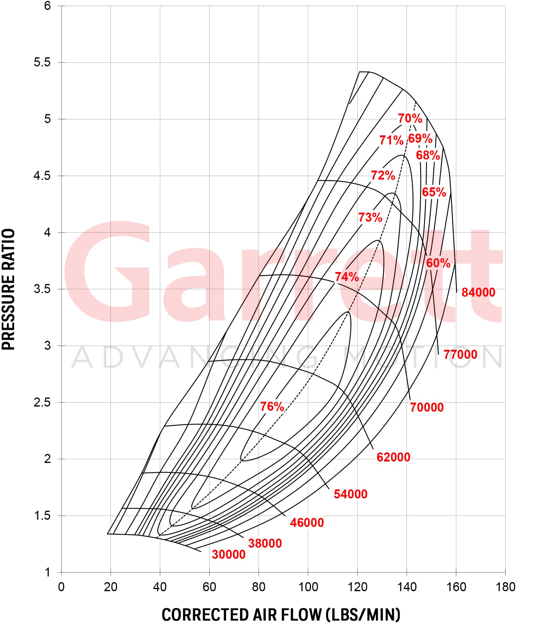
Since this is a scroll type compressor I cannot use the C5-impeller pump example exactly. I cannot do global rotation, instead I have used a rotating region with both local averaging (which usually makes better results) and sliding mesh (which takes 10 times or more longer to calculate, but comes up with very similar numbers). All of the scenarios described below do not care about the mesh density: I can run a 50,000 cell or a 2 million cell simulation and these same trends show up.
I have a 3d scan that was fully surfaced modeled in and doctored up to work nicely in flow simulation. However my problem stems from the inlet flow conditions.
If I use the flow conditions of inlet volume flow and environmental pressure outlet (like in the pump example file) then the inlet pressure skyrockets to thousands of psi. This obviously means my math is incorrect and that it is choking hard, however this still occurs when I use volume flow numbers taken from the Inlet mass flow conditions, or even divide them in half. I have only seen things like this occur in blocked outlet simulations.
Conversely if I use an inlet mass flow and environmental pressure outlet, the inlet pressure spikes a little above atmosphere (1-2psi) but not by much. Still this indicates the compressor is choked, however these are at flow conditions found in the middle of the compressor map, the compressor should not choke.
If I set both inlet and outlet to the same pressure, the flow will be in the correct direction and the mass flow/volume flow are all decently correct, however obviously the outlet pressure is wrong, even though the pressure locally coming off of the blades is right around what I would expect.
All of the inlet environmental pressure and outlet mass/volume/velocity are wrong, because they straighten out the flow locally near the exit since it is essentially like putting a vacuum hose to the outlet. Radial compressor will spin the air in the scroll, and this will continue into the outlet.
A dual environmental pressure condition is the most accurate since I only know the inlet pressure and temperature (atmospheric) and the outlet flow conditions are known from the choked turbine upstream of this compressor (found either on a chart or from turbine simulations). However, the flow starts positive (with about 20% the expected mass flow) and then quickly changes direction and surges heavily (to about -50% the expected mass flow).
I have tried looking up similar scenarios, and I have seen backwards flow that happens because Solidworks will default the flow to move in the direction of the pressure difference.
Is there a way to specify an initial mass flow approximation or force a direction of flow on an environmental pressure?
Thank you